Tuesday, December 21, 2010

Sometimes the best solutions are the simplest ones.

To solve the problem of knowing when the speed controllers are initialized or not, I decided that the best solution to solve the problem would be to use a current sensor. So I bought a current sensor. But unfortunately this solution has proved difficult to implement since the sensor is not working as I expected. To test the sensor I connected it to a Arduino board. The first problem I encountered is that the sensor reads the same values, regardless of whether or not connected to a circuit. I also tried to calibrate the sensor by following the procedure that is on the product page but without success. The second problem has to do with the little information available about this sensor.
However, while I tried to solve the sensor problem I found a simple solution to the problem of whether the speed controllers were initialized or not using only one on-off switch push. There is a switch designated switch DPST (Double Pole, Single Throw), which consists of a pair of on-off switches which operate together but in different circuits. The quadcopter has two independent circuits, one connecting the motors and speed controllers to one battery and other circuit that connects the Seeeduino board to the other battery. To test the idea I had based on this example from the page of the Arduino board. I designed a scheme that can be seen in figure 1 and that lets me know when the green LED is turned on or off.
Figure 1
As can be seen in the scheme of the figure 1 there are two independent circuits. One include the 9V battery and the LED and the another is on the Arduino board. Both circuits are connected to the on-off switch push. The following sketch lets me know at any moment if the LED is turned on or off.
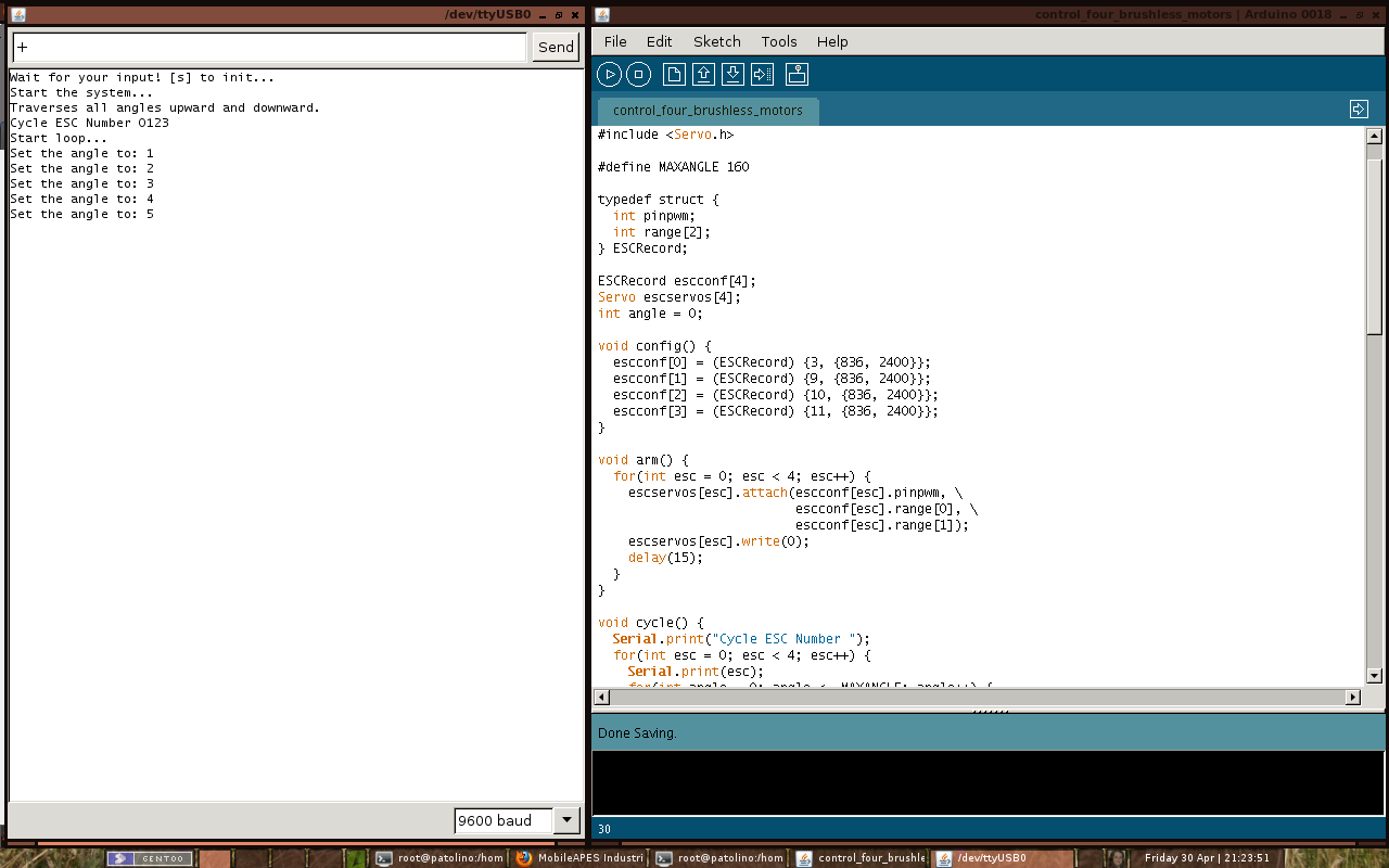
#define SWITCHPUSH 7  // the input pin where the
                      // on-off switch push is connected

int state = -1;   // state variable will be used to store
                  // the state of the input pin

void setup() {
  Serial.begin(9600);          // open the serial port
  pinMode(SWITCHPUSH, INPUT);  // tell Arduino SWITCHPUSH is an input
}

void loop() {
  int val = digitalRead(SWITCHPUSH);  // read input value
  
  // check if the read value is different of the state value
  if(val != state) {
    // check whether the input is HIGH (switch push pressed)
    if(val == HIGH) {
      // print the string "LED is ON" to the serial port
      Serial.println("LED is ON");
    } else {
      // print the string "LED is OFF" to the serial port
      Serial.println("LED is OFF");
    }
    state = val;  // store the value read in state variable
  }
  delay(100);  // wait 100 ms between each send
}
If I press the on-off switch push turns on the LED. From the Arduino board I get to know that the LED is turned on. If I turn off the Arduino board and re-connect it again I continue to know the status of the LED, because the on-off switch push operating in different circuits. This is very simple.
Figure 2
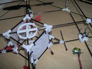
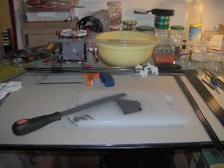
In Figure 2 we can see the two circuits with the various components in operation. The on-off switch push is in the image upside down so we can see the connections. By comparison we can see the LED as the speed controller. Sometimes the best solutions are the simplest ones.

Monday, November 29, 2010

The ACS712 Low Current Sensor Breakout has just arrived.

As I have mentioned before in a previous post, in order to make working the speed controllers it is necessary to initialize them first. This requires that previously the main board (Seeeduino Mega board) has been switched on, as it is the main board that makes the initialization. This procedure gives no problems when the sequence between the connections of the main board and the speed controllers is respected. However, if for any reason the main board have been previously switched on and after that it is switched off and then switched on again, the initialization happens twice even the speed controllers have already been initialized. This is because the status of the controllers it is not known and thus the motors can run up to the maximum speed. Therefore one needs a current sensor to detect whether the speed controllers are either switched on or off. I have  selected the sensor "ACS712 Low Current Sensor Breakout" which can be seen in the picture above. More information about this sensor can be found on page of its manufacturer. One of its advantage is that one can use it for example, to monitorize the power consumption of motors.

Friday, November 26, 2010

How to convert a string of Euler angles characters read by the 9DOF Razor IMU board into numeric values.

To guide the quadcopter in the space I will use the 9DOF Razor IMU board with the 9 Degree of Measurement Attitude and Heading Reference System (AHRS) code base. This board with AHRS code has the advantage of doing all the calculations and corrections for me. All I need to do is work out the interface. With the code one can chooses three options for receiving the data according to the constants that we define. If one sets the defined value "PRINT_DCM" to 1 then one will print the whole direction cosine matrix. If one sets the defined value "PRINT_ANALOG" to 1 then one will print the analog raw data. If one sets the defined value "PRINT_EULER" to 1 then one will print the Euler angles roll, pitch and yaw. These options are selected in the AHRS code before being compiled.
But first one needs to get the data in a format that can then be used by the Seeeduino Mega board to do the calculations to orient and stabilize the quadcopter. Reading the stream data from the 9DOF Razor IMU to the Seeeduino Mega board is a simple task and it has been shown in a previous post in which the data was transferred via a serial connection between the two boards - the diagram of the assembly can be seen in the image of the this previous post.
The data that I choose consist of the Euler angles roll, pitch and yaw and are sent by the 9DOF Razor IMU board sequentially in a text line. The line has the following format: "!ANG:0.00,0.00,0.00\r\n". To use the angles are necessary to split the line and then convert the numeric characters string parts to a numeric value (in this case a floating point number). After several failed attempts to read stream data sequentially I discovered that if I did not blocking the serial reads until the 9DOF Razor IMU board send the data often do not find the end of the text line which results in incorrect values and buffer overflow problems. To solve the problem of the serial reads may block permanently due to faulty connection with the 9DOF Razor IMU board was added a timeout. If at the end of the timeout has not been read the line the program continues its execution whiles keeping the previous angles values. This, procedure is important because if the Seeeduino Mega board lost the connection with 9DOF Razor IMU board the program can predicts code for example that here the motors are turned off and is activated a parachute, that save the quadcopter from crashing.
In the following sketch we can check the path followed to obtain the Euler angles in a numerical format from the 9DOF Razor IMU board.
#define TIMEOUT 100

// { roll, pitch, yaw }
float angles[3] = {0.0, 0.0, 0.0};

char read_char() {
  unsigned long starttime = millis();
  do {
    if(Serial1.available() > 0)
      return((char)Serial1.read());
  } while((millis() - starttime) < TIMEOUT);
  return NULL;
}

void get_angles() {
  for(int n=0; n<3; n++) {
    char buffer[9];
    int received = 0;
    char ch;
    do {
      if((ch = read_char()) == NULL) return;
    } while(ch != ',' && ch != '\r' && (buffer[received++] = ch));   
    buffer[received] = '\0';
    angles[n] = atof(buffer);
  }
}

void read_9dofahrs() {
  char beginstr[6] = {'!','A','N','G','\:','\0'};
  for(int i=0; i<5; i++)
    if(read_char() != beginstr[i]) return;
  get_angles();
}

void setup() {
  Serial.begin(57600);
  Serial1.begin(57600);
}

void loop() {
  read_9dofahrs();

  Serial.print(angles[0]);
  Serial.print(" | ");
  Serial.print(angles[1]);
  Serial.print(" | ");
  Serial.print(angles[2]);
  Serial.println("");
}
The result of this sketch can be seen in the following figure.

This short sketch will then be added to the main program that will control the stabilization and orientation in space of the quadcopter.

Sunday, November 21, 2010

Brushless Motors and Speed Controllers.

I am a beginner in electronics and although my skills are still basic, I am still searching documentation to see if I understand how I can properly put into operation one or more motors using the Arduino platform. In most open source quadcopter projects are almost always used the same speed controllers, however it should be possible to use any speed controller that works with a radio control (R/C).
I have been taking a look to several web sites and I have found that there were two main ways of how to communicate with speed controllers and put the motors running. One is to write a pulse width in microseconds directly to the i/o pins and the other is to use the Arduino "Servo" library or similar libraries like "SoftwareServo". In a previous post I have described how to put four motors running with the speed controllers that I have got for this project using the "Servo" library. Although, I have not investigated in depth the internals of the library I have noticed that the motor control is achieved by sending pulses to the speed controller or alternatively by sending an angle that can varies between 0º and 180º (the angle is converted internally to a pulse width in microseconds). However and for the speed controllers I am using, if I only send pulses to the i/o pins that will not put the motors in operation since the speed controllers need be initialized before using. So, in order to have more information available, I have downloaded of the speed controller specifications that I am using. After reviewing that document I have tried to develop an algorithm with the all steps to put the motors in operation. The procedure according to my adaptation of the document to initialize the speed controller is as follow (this procedure must be done before each use):
  1. Connect the Arduino board to the computer via USB to power up the board and set the pulse width value of the stop position on output pin (the stop position must be within the range 800 us to 1700 us for my speed controller). This procedure is like move the throttle stick to the desired stop position, and switch on the transmitter.
  2. Connect now the flight battery to the speed controler. The motor responds with 2 x beep.
  3. Increase the pulse width value (microseconds) in one unit on output pin until the motor responds with 3 x beep (the full-throttle position must be at least 350 us greater than the stop position). This is like move the throttle stick to the desired full-throttle position.
  4. Set again the pulse width value of the stop position on output pin. This procedure is like move the throttle stick to the desired stop position.
  5. If you now increase the pulse width value on output pin the motor will start running. This is like move the throttle stick from the stop position towards full-throttle.
I tried to implement the two methods described above but the only one that worked was the method that uses the library "Servo". The implementation of the procedure is now shown:
/*

  Motors: 4 x ROXXY 2827-34
  ___ESC: 4 x Roxxy BL-Control 818
  _Board: Seeeduino Mega v1.1
  
  ATENTION: Do not put the propellers in motors because this
            sketch is not well tested and can cause damage.
  
*/
#include <Servo.h>

// Set the pulse width value of the stop position to mid-point (1250 us).
#define STOPPOSITION          800+(1700-800)/2
// The full-throttle position must be at least 350 us greater
// than the stop position (1600 us).
#define FULLTHROTTLEPOSITION  STOPPOSITION+350
// My upper speed limit for safety.
#define MAXTHROTTLEPOSITION   FULLTHROTTLEPOSITION-100
// Create servo object to control four motors
Servo escservos[4];
// Variable to store the temporarily pulse width value.
int usvalue = STOPPOSITION;

void programpositions() {
  Serial.println("Type the character [p] to program the Stop and");
  Serial.println("Full-Throttle positions after connect the flight");
  Serial.println("battery to the ESC's.");
  Serial.println("The motor responds with 2 x beep.");
  Serial.println("");
  Serial.println("Type the character:");
  Serial.println("[+] to increase the pulse width value.");
  Serial.println("[-] to decrease the pulse width value.");
  Serial.println("[0] to set the pulse width value to stop position.");
  
  // Wait until get the input from the user.
  while(Serial.available() <= 0) {
    // Set the pulse width value of the stop position on output pins.
    for(int s=0; s<4; s++)
      escservos[s].writeMicroseconds(STOPPOSITION);
  }
  
  char ch = Serial.read();
  if(ch == 'p') {
    // Increase the pulse width value in one unit on output pins.
    // Exactly after a pulse width of the 350 microseconds from
    // the stopping position the motor responds with 3 x beep.
    for(int us=STOPPOSITION; us<=FULLTHROTTLEPOSITION; us++)
      for(int s=0; s<4; s++)
        escservos[s].writeMicroseconds(us);
    delay(5000);
  }
}

void set_speeds(int servo, int usvalue) {
  escservos[servo].writeMicroseconds(usvalue);
}

void setup() {
  Serial.begin(9600);
  
  // Attaches the ESC's on pins 2, 3, 4 and 5 to the servo object.
  for(int s=0; s<4; s++)
    escservos[s].attach(s+2, STOPPOSITION, FULLTHROTTLEPOSITION);
  
  programpositions();
}

void loop() {
  if(Serial.available()) {
    char ch = Serial.read();
    if(ch == '+') {
      // Increase the pulse width value.
      // The motor only starts running after increased up to 40 us.
      usvalue++;
      if(usvalue > MAXTHROTTLEPOSITION)
        usvalue = MAXTHROTTLEPOSITION;
    } else if(ch == '-') {
      // Decrease the pulse width value.
      usvalue--;
      if(usvalue < STOPPOSITION)
        usvalue = STOPPOSITION;
    } else if(ch == '0') {
      // Set the pulse width value to the stop position.
      usvalue = STOPPOSITION;
    }
    Serial.println(usvalue);
  }
  for(int s=0; s<4; s++)
    set_speeds(s, usvalue);
}
This implementation works very well for my speed controllers, but for other speed controllers the implementation will probably be different. The difference to the previous post is that instead using the value of the angles, I have used the pulse width value in microseconds and the delay after sending the angle has been removed. One immediate problem is that the Arduino board must always be connected before the speed controller which requires that board will check if the speed controller is switched on or off. If the speed controller is already connected and initialized and if for any reason you switched off the board and switched it on again, the motor can speed up to full speed because the speed controller was already set up, but as the board does not recognize it, it will make a new initialization. Therefore it is necessary to send a character to do or not the initialization of the speed controller. To solve this problem it is necessary a current sensor which will check whether the speed controller is switched on or off.

Wednesday, November 17, 2010

How to Upgrade 9DOF Razor IMU Test Firmware.

When I got the 9DOF - Razor IMU board I tried to upgrade the "Test Firmware" using the "Makefile" from the zip file but without success. So I sent an email to the Sparkfun tech support for them to verify what I was doing wrong. Today I finally got the answer and the best way to upgrade the firmware is upgraded manually.
The first step is to connect the 9DOF - Razor IMU board to FTDI Basic Breakout - 3.3V board following the diagram showed in Figure 1 from the post "How to upload 9DOF AHRS code". The second step is download the latest code from the git repository and execute the following commands (the commands were executed in a terminal on a machine with the Linux OS):
$ mkdir tmp
$ cd tmp
$ wget --no-check-certificate https://github.com/a1ronzo/\
SparkFun-9DOF-Razor-IMU-Test-Firmware/raw/master/9DOF-v18/9DOF-v18.zip
$ unzip 9DOF-v18.zip
$ make all
$ avrdude -p atmega328p -P /dev/ttyUSB0 -c stk500v1 -b 57600 \
-U flash:w:main.hex

avrdude: AVR device initialized and ready to accept instructions

Reading | ################################################## | 100% 0.02s

avrdude: Device signature = 0x1e950f
avrdude: NOTE: FLASH memory has been specified, an erase cycle will be
         performed
         To disable this feature, specify the -D option.
avrdude: erasing chip
avrdude: reading input file "main.hex"
avrdude: input file main.hex auto detected as Intel Hex
avrdude: writing flash (9156 bytes):

Writing | ################################################## | 100% 2.99s

avrdude: 9156 bytes of flash written
avrdude: verifying flash memory against main.hex:
avrdude: load data flash data from input file main.hex:
avrdude: input file main.hex auto detected as Intel Hex
avrdude: input file main.hex contains 9156 bytes
avrdude: reading on-chip flash data:

Reading | ################################################## | 100% 2.28s

avrdude: verifying ...
avrdude: 9156 bytes of flash verified

avrdude: safemode: Fuses OK

avrdude done.  Thank you.
Open now the Arduino IDE and click on "Serial Monitor" icon or from the "Tools" menu select the item "Serial Monitor". Set the baud rate to 38400 and verify if the "9DOF IMU Firmware v18" menu is showed (Figure 1).
Figure 1
It's not straightforward to save the previous firmware directly from the AVR. It's easier to keep the older .hex files around if I need them.

Wednesday, November 10, 2010

How to upload 9DOF AHRS code.

Figure 1
The first step is to connect the 9DOF - Razor IMU board to FTDI Basic Breakout - 3.3V board following the diagram showed in Figure 1. Then download the latest code from the sf9domahrs Google Code repository and uncompress the zip file. Change to the directory SF9DOF_AHRS, and open the SF9DOF_AHRS.pde file in Arduino IDE (0021).
Figure 2
After opening the file will be visible seven tabs (SF9DOF_AHRS, ADC, Compass, DCM, I2C, Output, Vector and matrix) like as shown in Figure 2. Select from the "Tools" menu and then from the "Board" submenu the board Arduino Pro or Pro Mini (3.3 V, 8Mhz) w/ AtMega328 which corresponds with the 9DOF - Razor IMU board.
Figure 3
Compile the code with the Arduino IDE and upload it to the 9DOF - Razor IMU board. Open the Serial monitor, set the baud rate to 57600 and verify if the data are coming (Figure 3), and voila, it's everything that has to do with it.

Saturday, November 6, 2010

Read 9DOF Razor IMU data via Seeeduino Mega board (Arduino Mega clone).

Figure 1
Read the data from the 9DOF Razor IMU board is very simple, but first I had to solder the pin-headers on the Seeeduino Mega board since the board is not sold with the pin-headers soldered, and then I connected the Seeeduino Mega board to the 9DOF Razor IMU board according to the diagram in Figure 1. Below is shown the sketch that allows you to read the data, as can be seen is short and simple.
/*

Read 9DOF Razor IMU data via Seeeduino Mega board (Arduino Mega clone).

1. Connect the jumper wires between the two boards
   according to the following table:

9DOF Razor IMU | Seeeduino Mega
---------------|--------------------
TX0............|RX1..(pin 18).......
RX1............|TX1..(pin 19).......
3.3V...........|3V3.................
GND............|GND.................
---------------|--------------------

2. Connect the USB Cable between the PC and the Seeeduino Mega board.
3. Select the "Board" item from the "Tools" top menu and check the radio
   button Arduino Mega (ATmega1280). 
4. Upload this Sketch to the Seeeduino Mega board
5. Open Serial Monitor and set the Baud rate to 57600.
6. Send the character '0' to view the 9DOF Razor IMU Menu.

9DOF IMU Test Firmware v15
==========================
[1]Accelerometer: ADXL345
[2]Magnetometer: HMC5843
[3]Gyroscope: LPR530 and LY530
[4]Raw
[5]Self Test

 */

void setup() {
  Serial.begin(57600);
  Serial1.begin(38400);  // Baud rate fixed....
  Serial1.print(4);      // Begin with Raw data
}

void loop() {
  if(Serial.available() > 0) {
    int incomingByte = Serial.read();
    /*
       DEC - BYTE
         0 - 48
         1 - 49
         2 - 50
         3 - 51
         4 - 52
         5 - 53
    */
    if(incomingByte >= 48 && incomingByte <= 53)
        Serial1.print(incomingByte, BYTE);
  }
  
  if(Serial1.available() > 0)
    Serial.print(Serial1.read(), BYTE);
}
After making the upload of the sketch, for the Seeeduino Mega Board, I opened the serial monitor and selected the baud rate to 57600 and can immediately observe the raw data to arrive (Figure 2).
Figure 2
To view the menu with more options, send the character "0". More options available can be seen in the sketch above. If you choose the Self Test (#5 in the Menu) and you always get a "MAG: BAD" message don't worry, probably your 9DOF Razor IMU board has no problem. Try upload the sketch, but where the first menu item to send is #5 (Self Test) instead of #4 (Raw) and you will see that the result will be different.

Monday, November 1, 2010

Now I can say that the frame is finished.

Figure 1
In the figure 1 can be seen the finished frame. The sides (white square mesh) of the central box that are not fixed to show the interior. I'm not sure the final weight of the frame without the components since I do not have a scale to weigh the frame with rigor. However, I can say that is extremely lightweight. Another aspect of the design I wanted to see was the box with all the plastic parts in black. The reason that I chose the white plastic instead of black plastic material, is because the black plastic is more expensive than the white plastic.
Figure 2
In the figure 2 we can see the landing gear finalized. I opted for a rigid structure that is easy to build, but is not a good solution since there is no damping of the structure during landing. So the landing must be extremely smooth to avoid damaging the frame.
Figure 3
In the figure 3 we can see the frame on its side to see the underside and is now clearly visible the landing gear. The landing gear is held rigid by tension with the green line from the kites.
Figure 4
Finally, in the figure 4 we can see the 9DOF Razor IMU board already on the place at the base of the central box. The next step is to link all the components and start programming.

Sunday, October 17, 2010

Missing parts to finish the frame.

I finally ended up drawing the missing parts to finish the frame. The new parts can be seen in the figure above. The part referenced by the letter "a" will serve to make the landing gear. After considering several solutions to the landing gear, I came to the conclusion that for now it is better to opt for a rigid structure rather than a solution with moving parts. The part referenced by the letter "b" will serve to support the boards. I even thought about using plastic hex standoffs, but as the Seeeduino Mega board only has three holes it was not very stable. Finally, the part referenced by the letter "c" will serve to make a plastic tensor for the yellow kite line with the black nylon cable ties. This part will replace the current tensor since it uses a metal ring to tighten the kite line so it does not come off.

Tuesday, October 5, 2010

The frame building is almost done.

Figure 1
As can be checked through the picture, the frame is almost ready. The original draft was changed a bit very recently. In the figure 1, we can see that three of the four motors are already put in the right place. At the point where the motor was not placed you can see the motor mount (black piece with screws not screwed). In the union between the plastic parts that form the structure where the engine will be screwed is placed a square of rubber to prevent the motion of this structure. The union of the whole frame is made with black nylon cable ties and kite line.
Figure 2
The walls of the central box (Figure 2) are made with square mesh like the one used in balconies, terraces and garden fencing. The mesh is also attached to the carbon tubes with black nylon cable ties.
Figure 3
Figure 3 shows in more detail the central box where all the electronics will be put in. We can also see the speed controller already placed inside the center box and attached to the square mesh wall. The landing gear of the original project has also been modified as it was too complex. A new simpler version has been planned.

Thursday, September 30, 2010

The clone of the Arduino Mega board just arrived.

I just got the clone of the Arduino Mega board that I have ordered to solve the problem of how to connect more than one Serial device. After some research, I have concluded that the best choice is the Seeeduino Mega board because of it is totally compatible with most Arduino Shields, it is flat form factor and small (similar size to the Arduino Duemilanove board, but 30% smaller than the Arduino Mega), it has 4 UARTs (hardware serial ports) and 70 digital input/output pins, and it is not very expensive. Meanwhile it has the disadvantage that one has to solder the pin-headers.
In this link you can see the differences between the Seeeduino Mega and the Arduino Mega board.

Monday, September 27, 2010

Start assembling the new frame.

I have started to assemble another version for the frame. Hope this will be the last one :-). The first step was to cut the carbon tubes and to do this ,I used a plastic ruler and a saw with a small blade to cut metal. To adjust the sizes of the tubes I used a rasp tool for metal and a fine grit sandpaper for metal.
Figure 1
The Figure 1 shows the work in progress and the tools, as well as several carbon tubes already cut. It is also important to have at hand a vacuum cleaner to clean the carbon dust that is produced during the cutting and sanding and do not forget to put a mask because of dust.
Figure 2
In Figure 2 we can see the bottom of the frame now with the plastic pieces placed in appropriate locations.
Figure 3
In the last figure (Figure 3) we can see the bottom and the top of the frame. Nowhere in the construction glue is used to connect the different parts. To keep the tubes attached to the pieces I used kite line (the green line in figure 2 and 3) and the white nylon cable ties. I will continue to assemble the frame. Hope it will be ready this week!

Monday, September 20, 2010

Read data from the 9 DOF Razor IMU via Arduino board.

After several problems with the original 9DOF Razor IMU board, I have finally got a board with no functional problems or bugs. The challenge we had to work around then was how to read the data from the board? So I decided do some research and found in this blog that there was a simple way to read data using the Arduino Duemilanove connected to the 9DOF Razor IMU board without requiring any additional cable as shown in Figure 1.
Figure 1
The sketch to read the data from the 9DOF Razor IMU via Arduino Duemilanove is very short and simple as shown below.
/*

Read data from the 9DOF Razor IMU board via arduino duemilanove board.

1. Upload this Sketch to the Arduino board
2. Disconnect the USB cable from the PC. 
3. Connect the jumper wires between the two boards
   according to the following table:

9DOF Razor IMU | Arduino Duemilanove
---------------|--------------------
TX0............|TX1.................
RX1............|RX0.................
3.3V...........|3V3.................
GND............|GND.................
---------------|--------------------

4. Connect again the USB Cable to the PC.
5. Open Serial Monitor.
6. Send the character '1'.
7. Send the character '0' to view the 9DOF Razor IMU Menu.

*/

void setup() {
  Serial.begin(38400);
}

void loop() {
  if(Serial.available()) {
    Serial.print(Serial.read(), BYTE);
  }
}
After doing the upload of the sketch, and open the Serial Monitor, send a character between '1' and '5' followed by a '0' then a menu is shown (Figure 2).

Figure 2
In the menu there are have five options: [1] Accelerometer (ADXL345), [2] Magnetometer (HMC5843), [3] Gyroscope (LPR530 and LY530), [4] Raw and [5] Self Test. For example, if you choose the option "1" and if you move the 9DOF Razor IMU board in any direction you will see on the Serial monitor the variation of the values for the aceleration
The following video shows the 9DOF Razor IMU board connected to the Arduino board working hard (Sorry for the bad video quality!). Notice menu of the 9DOF Razor IMU board on the monitor of the laptop.
But unfortunately this sketch does not fit what I want. With the Arduino Duemilanove only can be used a single Serial connection at a time. However, that problem can be solved by using software libraries. One of the libraries is the SoftwareSerial library which allows the serial communication on any of the Duemilanove's digital pins. But, because it's not supported by hardware, the library has a few limitations. The other library is the NewSoftSerial library that emulates an additional serial port, allowing you to communicate with another Serial device. However, there is another Arduino board where you can use more than one connection, which is the Arduino Mega. With the Arduino Mega is possible connect more three Serial devices. The last solution is more robust but, requires a further investment in a new board. So I'll have to take a look in the Arduino board clones.

Tuesday, September 14, 2010

Building quadcopters for impatient people.

Image from the instructables.com site.
On Sunday I have received a newsletter from the website "Instructables.com" and one of the articles was about a school class who made a fully functional quadcopter in only 4 weeks using the arduino board and standard RC equipment. All the stages of its construction can be followed on this page of the website "Instructables.com". The code is also available. The video of the quadcopter, also including other projects, can be viewed at this link.

Monday, September 13, 2010

Fuzzy Logic Control.

While I was looking for information about PID controllers I have found the so called Fuzzy Logic method. Even it is a quite old method it has not been explored well enough. It can solve problems by using non-well-precised information, similarly to what happens when human brain has to make a decision. Thus, things like knowledge and daily experiences, coming for example from human feelings to temperature, light, etc, can be mapped into an abstract knowledgement such as exact numeric ranges as in this C# code example. In the real world most of the systems have nonlinear behaviors or are difficult to linearize, so is it here that this methodology is an alternative to traditional control methods. On this link you will find a more detailed explanation for its use. For myself it seems to be easier to understand and implement than a PID controller. I have found this paper with a practical application of that method to an autonomous robot obstacle avoidance, but one can be found many more examples of applications in different areas.
After a search on google I have found several libraries to implement this methodology:

Tuesday, September 7, 2010

Inspection of the plastic parts.

After some holidays I am finally back to work. The first task was to check the size of plastic parts and test their resistance to shock and traction.  I have noticed that the carbon tubes and the holes of the plastic parts do not fit as they have different sizes. Although this is an easy problem to solve by using a proper drill to increased the holes of the parts. Thus for further reference the tolerance of the holes must be increased by some millimeters.
The plastic parts are well resistant to shock as there is no visible damage when dropped from the second floor of a building to its ground floor. This test is also known as naive test :-). They are also well resistant to traction as the nylon thread used on the traction did not break the plastic part.
Therefore, the plastic parts we are using are suitable for the construction of the quadcopter. Now I'll have to order the other parts to complete the frame.

Sunday, July 25, 2010

Finally the samples of the parts came from the Shapeways.

Figure 1
Finally, after a long wait the samples of the parts arrived. I have just unpack the parts and after a detailed analysis I was amazed at the quality and detail of them.
Figure 2
The material is lightweight and hard, but have a rough surface. These parts are samples to see if they were as planned. After checking the measures and their resistance, then I'll order the rest. I hope not to make any changes in any part.

Saturday, July 3, 2010

3D frame with parts.

Figure 1
Here is the frame with the all parts placed in appropriate locations. This model took about an hour to be generated on my laptop with OpenSCAD software. For the set does not separate the parts have holes for the cables ties which will keep the parts in place.

Figure 2
A view from the under the frame can be seen in Figure 2. In this figure we can see the "landing gear" in more detail.

Figure 3
In figure 3 we can see a side view in perspective of the frame, as well as all the "landing gear".

Figure 4
Finally, the figure 4 shows in detail the central cube of the frame, where we put all the electronic components. Now, as soon as possible and I will order some parts to see if they match the parts designed.

Monday, June 28, 2010

The skeleton of the frame in 3D.

Figure 1
After several days around the OpenSCAD software, the skeleton of the frame in 3D without the parts are ready. The figure 1 shows the position of carbon tubes with the final dimensions. The letters point to tubes with different lengths. The list with lengths can be found in this pdf file.
Figure 2
The figure 2 shows a top view of the skeleton of the frame. From above we can see that the frame is based on three squares.

Figura 3
The figure 3 shows a side view of the skeleton of the frame. In this figure we can see the tubes that will serve as the "landing gear".
As can be seen by the figures the frame is very simple. The next step is to put the parts in the skeleton to get the complete frame.

Wednesday, June 9, 2010

Plastic parts to assemble the frame of the quadcopter.

All plastic parts to assemble the frame of the quadcopter were modeled in 3D using the software OpenSCAD. I also created a repository where I put the source code files for use with OpenSCAD and the STL (Stereolithography File) files to use for those who want to print the parts in a 3D printer. I also discovered a site that prints the parts from the STL files for a reasonable price! The list of parts with the dimensions can be found at the site Shapeways, if you search for "mobileapes". Alternatively, the list of parts can be found in this pdf file. The material selected to make the parts is the "white strong & flexible" nylon , which is the cheapest. Those who prefer may choose the "black strong & flexible" nylon, once the carbon tube is black, but this option is more expensive.

Saturday, May 29, 2010

Aggressive Maneuvers for Autonomous Quadrotor Flight.

The video above shows a spectacular quadcopter. An authentic acrobat of the air. Demonstrations of pirouettes, flips, flight through windows, and quadrotor perching are shown. This spectacular device was developed at at the GRASP Lab, University of Pennsylvania. More information can be found at this site.

Thursday, May 20, 2010

The first part of the quadcopter in 3D.

After some research I found several people who have 3D printers. I also discovered that there are sites that print the parts if we uploading the file with the 3D model and then send them by regular mail after printed. In many sites, you can also choose the material we want that our parts be printed.
Figure 1
I tried three 3D modeling tools available for Linux, Blender, Wings 3D and OpenSCAD. I found that the Blender is a complex tool but at the same time powerful, but requires a lot of learning for a beginner. Wings 3D is very easy to use but it is very difficult when you have to make the so called Boolean operations, ie, unions, subtractions and intersections. Finally, the OpenSCAD, is not a tool so much known, but it is a tool that does just the job I wanted to do, that is to make a 3D model for printing. The OpenSCAD uses a very simple scripting language for creating 3D models of parts. An example can be seen in Figure 1.
Figure 2
In Figure 2 we can observe the same part shown in Figure 1 with some minor differences, but made using the Wings 3D. An interesting use of the various tools is to use OpenSCAD to create the initial 3D model and then refines it with more detail using the Wings 3D or the Blender.
Another problem we have keep in mind when modeling the parts to print is to make a support for the parts if, the parts does not have a base for maintaining the equilibrium, to ensure that the parts does not move while being printed.

Friday, May 14, 2010

Finally, I got the 9 DOF Razor IMU board.

Yes, the 9 DOF Razor IMU board finally arrived. It is really very small. The three sensors, aceleromentro, gyroscope and compass in a single small board. The data provided by this board will be responsible for 3D orientation and stabilization of the quadcopter in the air. I already have some ideas of how to connect this board to the Arduino board. The following post published in the Arduino forum indicates a path to follow to read the data from the Arduino board. But after a quick search, I found there is not much information on how to use this board.

Monday, May 10, 2010

3D printer for rapid prototyping.

While I wait for the new electronic parts to arrive, I found a printer that prints 3D plastic objects. The most amazing thing is that extremely cheap compared to the price of industrial printers for rapid prototyping. This type of printer is more like a desktop printer. Some 3D printers, are open source community projects like the RepRap project. The following video shows how the RepRap 3D printer works.
The parts for the quadcopter were made by hand and they look rough. But with a 3D printer I can quickly make the parts and reduce the weight by replacing metal parts with plastic. I can also do more aerodynamic parts. To make the parts, it is necessary first to model the parts in a 3D software like Blender, Wings 3D or OpenSCAD and then save in a format that can be read by the 3D printer, usually in a stereolithography file (stl). Now I have to find someone who has a 3D printer near where I live that can print the parts, but first I have to model each part of the quadcopter in 3D. But it would be interesting to make a kit that people could then print and assemble using a 3D printer.

Wednesday, May 5, 2010

The best combination of sensors to make a flight controller.

To stabilize and guide the quadcopter autonomously - independent of the algorithms they are used - it needs the combination of multiple sensors. Initially, it will use an accelerometer, a gyroscope and a compass. To guide him inside of the buildings will use ultrasonic sensors. A simple GPS, will guide the helicopero between two points in outdoor environment.
After doing some research, I came to the conclusion that the best combination would be to use the board "IMU 6DOF Razor - Ultra-Thin IMU" with the board "Triple Axis Magnetometer Breakout - HMC5843". The first board makes use of ST's LPR530AL (pitch and roll) and LY530ALH (yaw) gyros, as well as the ADXL335 triple-axis accelerometer, to give six degrees of measurement. The second board is a breakout board for Honeywell's HMC5843, a 3-axis digital compass. Communication with the HMC5843 is simple and all done through an I2C interface. The two boards together provide nine degrees of measurement.
But when I had already decided by the combination indicated above, I discovered the same combination, but which joins the three sensors (aceleromentro, gyroscope and compass) in a single board. The board “9 Degrees of Freedom - Razor IMU - AHRS compatible” incorporates the same four sensors of the boards described above - an LY530AL (single-axis gyro), LPR530AL (dual-axis gyro), ADXL345 (triple-axis accelerometer), and HMC5843 (triple-axis magnetometer) - to give nine degrees of inertial measurement. The outputs of all sensors is processed by on-board ATmega328 and sent out via a serial stream. I think this is will be the best solution for an autonomous quadcopter.

Monday, May 3, 2010

What I've done until now.

The diagram above shows what I have been doing since I have started the motor controller. Indeed, it is still only a little bit. The most important part of the work will start now with the design and implementation of the flight controller. The first challenge is to deeply understand the dynamics of a “quadcopter” flight and then select the most appropriate control algorithms.
Basically, the quadcopter is an aerial vehicle and consists of a rigid frame with four motors mounted in the arms of the cross. Two pairs of perpendicular propellers rotate in opposite directions, one pair in a clockwise direction and another in the counter clockwise. When one varies the speed of a motor can change the lift and create motion, as well as increasing or decreasing the speed of the four propellers together generate a vertical motion. Changing the speed of the pair of propellers that run in a counter clockwise direction reciprocally produces roll rotation, along with lateral motion. Likewise, changing the speed of the pair of propellers, that run in a clockwise direction reciprocally produces the pitch rotation and the longitudinal motion. The difference in the counter-torque between each pair of propellers have as a result the yaw rotation.

Friday, April 30, 2010

Control all four motors from the arduino board with ESC's.

After some research I was able to control all four brushless motors from the arduino board with four speed controllers, one for each motor. The sketch can be seen in detail below.

Figure 1
The figure 1 shows the arduino development environment. In the left window (Serial Monitor) you can see the result of the instructions sent to the arduino board via serial port (USB-serial device). When the quadcopter is switch on must be sent the character "s" to initialize the speed controllers. After the controllers initialized, do not re-send the character "s" in any circumstance, if you send the motors immediately accelerated to full speed in less than 1 second. If you have placed the propellers in the motors of the quadcopter, then you'll see him being sent to the deep sky if you're a lucky guy. Here is the warning to anyone wishing to use this sketch. To increase the speed the character "+" is sent to the serial port and the character "-" to decrement the speed. To stop the motors the character "0" is sent.
Figure 2
The figure 2 shows how the speed controllers are attached to the side panels.
Figure 3
The figure 3 shows the cable connections of the speed controllers on board (Sorry for the bad image quality). When I have time I do a diagram of all connections.

#include <Servo.h>

#define MAXANGLE 160

typedef struct {
  int pinpwm;
  int range[2];
} ESCRecord;

ESCRecord escconf[4];
Servo escservos[4];
int angle = 0;

void config() {
  escconf[0] = (ESCRecord) {3, {836, 2400}};
  escconf[1] = (ESCRecord) {9, {836, 2400}};
  escconf[2] = (ESCRecord) {10, {836, 2400}};
  escconf[3] = (ESCRecord) {11, {836, 2400}};
}

void arm() {
  for(int esc = 0; esc < 4; esc++) {
    escservos[esc].attach(escconf[esc].pinpwm, \
                          escconf[esc].range[0], \
                          escconf[esc].range[1]);
    escservos[esc].write(0);
    delay(15);
  }
}

void cycle() {
  Serial.print("Cycle ESC Number ");
  for(int esc = 0; esc < 4; esc++) {
    Serial.print(esc);
    for(int angle = 0; angle <= MAXANGLE; angle++) {
      escservos[esc].write(angle);
      delay(15);
    }
    for(int angle = MAXANGLE; angle >= 0; angle--) {
      escservos[esc].write(angle);
      delay(15);
    }
  }
  Serial.println("");
}

void setup() {
  delay(1000);
  Serial.begin(9600);

  Serial.println("Wait for your input! [s] to init...");
  while(Serial.available() <= 0)
    delay(1000);
  int incomingByte = Serial.read();

  Serial.println("Start the system...");

  config(); 
  arm();
  delay(5000);

  if(incomingByte == 115) {
    Serial.println("Traverses all angles upward and downward.");  
    cycle();
    delay(1000);
  }
  Serial.println("Start loop...");
}

void setspeed(int angles[4]) {
  for(int esc = 0; esc < 4; esc++) {
    escservos[esc].write(angles[esc]);
    delay(120);
  }
}

void loop() { 
  if(Serial.available() > 0) {
    int incomingByte = Serial.read();
    if(incomingByte == 43)      // sends the character '+'
      angle++;                  // increases the speed
    else if(incomingByte == 45) // sends the character '-'
      angle--;                  // decreases the speed
    else if(incomingByte == 48) // sends the character '0'
      angle = 0;                // set the speed to zero
    
    if(angle < 0)
      angle = 0;
    if(angle > MAXANGLE)
      angle = MAXANGLE;
      
    Serial.print("Set the angle to: ");
    Serial.println(angle);
  }
    
  int angles[4] = {angle, angle, angle, angle};
  setspeed(angles);
}

Monday, April 26, 2010

Cables and more cables.

Finally silicone cables have just arrived. Now I can solder the connectors on the cables to connect all speed controllers (ESC) to the battery. I'll cut four red cables (0.75 qmm) that will connect a red cable (1 qmm) that will connect to the battery. Then I will have to do the same for the black cable. I also ordered the cable to connect the receiver connection from the speed controllers to the arduino board, but came with the wrong colors, orange, red and brown, but what I ordered was black, red and white. After some research on google I found that the colors depend on the manufacturer of the radio control (R/C). So the orange, white or yellow color is the signal (Pulse), the red color is the Positive, the brown or black color is the Negative (Ground). For the quadcopter I just need the white cable (orange or yellow) and the black cable (brown) from the all speed controllers.

Monday, April 19, 2010

Now you can follow the blog on twitter.

I have just started a MobileAPES account on "Twitter". If you are a “Twitter” fan, click on this link to follow this project. I will use this tool to keep the readers and followers of the blog up to date on the progress in building of the quadcopter.

Tuesday, April 13, 2010

Control a motor from the arduino board with a speed controller.

I connected the speed controller (ESC) to the arduino board and I connected the black cable of the receiver connection to the GND pin of the arduino and the white cable to the Digital PWM pin number 3.

I upload a sketch that I found on this post from the Arduino Forum to the board to test the motor, but nothing happening.
After some research I discovered that is necessary adjust the minim pulse width value. From the operating instructions that came with the speed controller I find that the stop position must be within the range 800 us to 1700 us and the full-throttle position must be at least 350 us than the stop position.
I make another sketch to find the the minimum pulse width value that start the motor and closer to the 0 angle. After several attempts I found that the nearest value is 836 us.
Finally, I made the sketch that is shown below, which starts the  ESC and keeps the motor running in a loop for 30 seconds and then stop for 10 seconds.

#include <Servo.h>

Servo escservo;

long lasttime = millis();

void setup() {
  delay(1000);
  Serial.begin(9600);

  // If you connected now the battery to the ESC, send
  // the 's' character. If not send another character.
  Serial.println("Wait for your input! [s] to init...");
  while(Serial.available() <= 0) delay(1000);
  Serial.println("Start the system...");
  int incomingByte = Serial.read();
  
  // Change the min pulse width value until match the
  // lowest value needed to start the motor.
  // From the ESC operation instructions the stop position
  // must be within the range 800 us to 1700 us.
  // The value 836 us is the lowest value.
  escservo.attach(3, 836, 2400);
  
  // arm the ESC
  escservo.write(0);
  delay(5000);
  
  // If you sent the character 's'
  if(incomingByte == 115) {
    Serial.println("Traverses all angles upward and downward.");
    cycle();
    delay(1000);
  }
}

void cycle() {
  int angle;
  // Danger: Try first with a value lower than 179, eg 160
  // Gradually increase to 180.
  for(angle = 0; angle <= 160; angle++) {
    escservo.write(angle);
    delay(15);
  }
  // Decrease the angle from 180 to 0.
  for(angle = 160; angle >= 0; angle--) {
    escservo.write(angle);
    delay(15);
  }
}

void loop() {
  long duration = millis() - lasttime;

  // If the duration is great than 30 seconds,
  // stop the engine for 10 seconds.
  if(duration >= 30000) {
    escservo.write(0);
    delay(10000);
    lasttime = millis();
  }
  // Put the motor to rotate in the angle 5
  escservo.write(5);
  delay(500);
}

Saturday, March 27, 2010

The brushless motors are mounted and connected to the speed controllers.

After a few hours spent soldering the connectors in the brushless motors and in the speed controllers, the brushless motors were mounted and connected to the speed controllers.
The next step is to cut the silicone cables and solder the connectors on the ends of each cable and then connect the cables from the four speed controllers to the Lipo battery.