 |
| Figure 1 |
Here is the frame with the all parts placed in appropriate locations. This model took about an hour to be generated on my laptop with OpenSCAD software. For the set does not separate the parts have holes for the cables ties which will keep the parts in place.
 |
| Figure 2 |
A view from the under the frame can be seen in Figure 2. In this figure we can see the "landing gear" in more detail.
 |
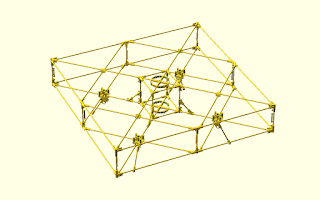
| Figure 3 |
In figure 3 we can see a side view in perspective of the frame, as well as all the "landing gear".
 |
| Figure 4 |
Finally, the figure 4 shows in detail the central cube of the frame, where we put all the electronic components. Now, as soon as possible and I will order some parts to see if they match the parts designed.


No comments:
Post a Comment