Monday, May 10, 2010

3D printer for rapid prototyping.

While I wait for the new electronic parts to arrive, I found a printer that prints 3D plastic objects. The most amazing thing is that extremely cheap compared to the price of industrial printers for rapid prototyping. This type of printer is more like a desktop printer. Some 3D printers, are open source community projects like the RepRap project. The following video shows how the RepRap 3D printer works.
The parts for the quadcopter were made by hand and they look rough. But with a 3D printer I can quickly make the parts and reduce the weight by replacing metal parts with plastic. I can also do more aerodynamic parts. To make the parts, it is necessary first to model the parts in a 3D software like Blender, Wings 3D or OpenSCAD and then save in a format that can be read by the 3D printer, usually in a stereolithography file (stl). Now I have to find someone who has a 3D printer near where I live that can print the parts, but first I have to model each part of the quadcopter in 3D. But it would be interesting to make a kit that people could then print and assemble using a 3D printer.

Wednesday, May 5, 2010

The best combination of sensors to make a flight controller.

To stabilize and guide the quadcopter autonomously - independent of the algorithms they are used - it needs the combination of multiple sensors. Initially, it will use an accelerometer, a gyroscope and a compass. To guide him inside of the buildings will use ultrasonic sensors. A simple GPS, will guide the helicopero between two points in outdoor environment.
After doing some research, I came to the conclusion that the best combination would be to use the board "IMU 6DOF Razor - Ultra-Thin IMU" with the board "Triple Axis Magnetometer Breakout - HMC5843". The first board makes use of ST's LPR530AL (pitch and roll) and LY530ALH (yaw) gyros, as well as the ADXL335 triple-axis accelerometer, to give six degrees of measurement. The second board is a breakout board for Honeywell's HMC5843, a 3-axis digital compass. Communication with the HMC5843 is simple and all done through an I2C interface. The two boards together provide nine degrees of measurement.
But when I had already decided by the combination indicated above, I discovered the same combination, but which joins the three sensors (aceleromentro, gyroscope and compass) in a single board. The board “9 Degrees of Freedom - Razor IMU - AHRS compatible” incorporates the same four sensors of the boards described above - an LY530AL (single-axis gyro), LPR530AL (dual-axis gyro), ADXL345 (triple-axis accelerometer), and HMC5843 (triple-axis magnetometer) - to give nine degrees of inertial measurement. The outputs of all sensors is processed by on-board ATmega328 and sent out via a serial stream. I think this is will be the best solution for an autonomous quadcopter.

Monday, May 3, 2010

What I've done until now.

The diagram above shows what I have been doing since I have started the motor controller. Indeed, it is still only a little bit. The most important part of the work will start now with the design and implementation of the flight controller. The first challenge is to deeply understand the dynamics of a “quadcopter” flight and then select the most appropriate control algorithms.
Basically, the quadcopter is an aerial vehicle and consists of a rigid frame with four motors mounted in the arms of the cross. Two pairs of perpendicular propellers rotate in opposite directions, one pair in a clockwise direction and another in the counter clockwise. When one varies the speed of a motor can change the lift and create motion, as well as increasing or decreasing the speed of the four propellers together generate a vertical motion. Changing the speed of the pair of propellers that run in a counter clockwise direction reciprocally produces roll rotation, along with lateral motion. Likewise, changing the speed of the pair of propellers, that run in a clockwise direction reciprocally produces the pitch rotation and the longitudinal motion. The difference in the counter-torque between each pair of propellers have as a result the yaw rotation.

Friday, April 30, 2010

Control all four motors from the arduino board with ESC's.

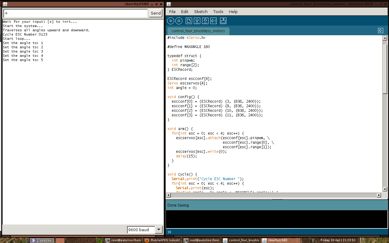
After some research I was able to control all four brushless motors from the arduino board with four speed controllers, one for each motor. The sketch can be seen in detail below.

Figure 1
The figure 1 shows the arduino development environment. In the left window (Serial Monitor) you can see the result of the instructions sent to the arduino board via serial port (USB-serial device). When the quadcopter is switch on must be sent the character "s" to initialize the speed controllers. After the controllers initialized, do not re-send the character "s" in any circumstance, if you send the motors immediately accelerated to full speed in less than 1 second. If you have placed the propellers in the motors of the quadcopter, then you'll see him being sent to the deep sky if you're a lucky guy. Here is the warning to anyone wishing to use this sketch. To increase the speed the character "+" is sent to the serial port and the character "-" to decrement the speed. To stop the motors the character "0" is sent.
Figure 2
The figure 2 shows how the speed controllers are attached to the side panels.
Figure 3
The figure 3 shows the cable connections of the speed controllers on board (Sorry for the bad image quality). When I have time I do a diagram of all connections.

#include <Servo.h>

#define MAXANGLE 160

typedef struct {
  int pinpwm;
  int range[2];
} ESCRecord;

ESCRecord escconf[4];
Servo escservos[4];
int angle = 0;

void config() {
  escconf[0] = (ESCRecord) {3, {836, 2400}};
  escconf[1] = (ESCRecord) {9, {836, 2400}};
  escconf[2] = (ESCRecord) {10, {836, 2400}};
  escconf[3] = (ESCRecord) {11, {836, 2400}};
}

void arm() {
  for(int esc = 0; esc < 4; esc++) {
    escservos[esc].attach(escconf[esc].pinpwm, \
                          escconf[esc].range[0], \
                          escconf[esc].range[1]);
    escservos[esc].write(0);
    delay(15);
  }
}

void cycle() {
  Serial.print("Cycle ESC Number ");
  for(int esc = 0; esc < 4; esc++) {
    Serial.print(esc);
    for(int angle = 0; angle <= MAXANGLE; angle++) {
      escservos[esc].write(angle);
      delay(15);
    }
    for(int angle = MAXANGLE; angle >= 0; angle--) {
      escservos[esc].write(angle);
      delay(15);
    }
  }
  Serial.println("");
}

void setup() {
  delay(1000);
  Serial.begin(9600);

  Serial.println("Wait for your input! [s] to init...");
  while(Serial.available() <= 0)
    delay(1000);
  int incomingByte = Serial.read();

  Serial.println("Start the system...");

  config(); 
  arm();
  delay(5000);

  if(incomingByte == 115) {
    Serial.println("Traverses all angles upward and downward.");  
    cycle();
    delay(1000);
  }
  Serial.println("Start loop...");
}

void setspeed(int angles[4]) {
  for(int esc = 0; esc < 4; esc++) {
    escservos[esc].write(angles[esc]);
    delay(120);
  }
}

void loop() { 
  if(Serial.available() > 0) {
    int incomingByte = Serial.read();
    if(incomingByte == 43)      // sends the character '+'
      angle++;                  // increases the speed
    else if(incomingByte == 45) // sends the character '-'
      angle--;                  // decreases the speed
    else if(incomingByte == 48) // sends the character '0'
      angle = 0;                // set the speed to zero
    
    if(angle < 0)
      angle = 0;
    if(angle > MAXANGLE)
      angle = MAXANGLE;
      
    Serial.print("Set the angle to: ");
    Serial.println(angle);
  }
    
  int angles[4] = {angle, angle, angle, angle};
  setspeed(angles);
}

Monday, April 26, 2010

Cables and more cables.

Finally silicone cables have just arrived. Now I can solder the connectors on the cables to connect all speed controllers (ESC) to the battery. I'll cut four red cables (0.75 qmm) that will connect a red cable (1 qmm) that will connect to the battery. Then I will have to do the same for the black cable. I also ordered the cable to connect the receiver connection from the speed controllers to the arduino board, but came with the wrong colors, orange, red and brown, but what I ordered was black, red and white. After some research on google I found that the colors depend on the manufacturer of the radio control (R/C). So the orange, white or yellow color is the signal (Pulse), the red color is the Positive, the brown or black color is the Negative (Ground). For the quadcopter I just need the white cable (orange or yellow) and the black cable (brown) from the all speed controllers.

Monday, April 19, 2010

Now you can follow the blog on twitter.

I have just started a MobileAPES account on "Twitter". If you are a “Twitter” fan, click on this link to follow this project. I will use this tool to keep the readers and followers of the blog up to date on the progress in building of the quadcopter.

Tuesday, April 13, 2010

Control a motor from the arduino board with a speed controller.

I connected the speed controller (ESC) to the arduino board and I connected the black cable of the receiver connection to the GND pin of the arduino and the white cable to the Digital PWM pin number 3.

I upload a sketch that I found on this post from the Arduino Forum to the board to test the motor, but nothing happening.
After some research I discovered that is necessary adjust the minim pulse width value. From the operating instructions that came with the speed controller I find that the stop position must be within the range 800 us to 1700 us and the full-throttle position must be at least 350 us than the stop position.
I make another sketch to find the the minimum pulse width value that start the motor and closer to the 0 angle. After several attempts I found that the nearest value is 836 us.
Finally, I made the sketch that is shown below, which starts the  ESC and keeps the motor running in a loop for 30 seconds and then stop for 10 seconds.

#include <Servo.h>

Servo escservo;

long lasttime = millis();

void setup() {
  delay(1000);
  Serial.begin(9600);

  // If you connected now the battery to the ESC, send
  // the 's' character. If not send another character.
  Serial.println("Wait for your input! [s] to init...");
  while(Serial.available() <= 0) delay(1000);
  Serial.println("Start the system...");
  int incomingByte = Serial.read();
  
  // Change the min pulse width value until match the
  // lowest value needed to start the motor.
  // From the ESC operation instructions the stop position
  // must be within the range 800 us to 1700 us.
  // The value 836 us is the lowest value.
  escservo.attach(3, 836, 2400);
  
  // arm the ESC
  escservo.write(0);
  delay(5000);
  
  // If you sent the character 's'
  if(incomingByte == 115) {
    Serial.println("Traverses all angles upward and downward.");
    cycle();
    delay(1000);
  }
}

void cycle() {
  int angle;
  // Danger: Try first with a value lower than 179, eg 160
  // Gradually increase to 180.
  for(angle = 0; angle <= 160; angle++) {
    escservo.write(angle);
    delay(15);
  }
  // Decrease the angle from 180 to 0.
  for(angle = 160; angle >= 0; angle--) {
    escservo.write(angle);
    delay(15);
  }
}

void loop() {
  long duration = millis() - lasttime;

  // If the duration is great than 30 seconds,
  // stop the engine for 10 seconds.
  if(duration >= 30000) {
    escservo.write(0);
    delay(10000);
    lasttime = millis();
  }
  // Put the motor to rotate in the angle 5
  escservo.write(5);
  delay(500);
}