Thursday, September 30, 2010

The clone of the Arduino Mega board just arrived.

I just got the clone of the Arduino Mega board that I have ordered to solve the problem of how to connect more than one Serial device. After some research, I have concluded that the best choice is the Seeeduino Mega board because of it is totally compatible with most Arduino Shields, it is flat form factor and small (similar size to the Arduino Duemilanove board, but 30% smaller than the Arduino Mega), it has 4 UARTs (hardware serial ports) and 70 digital input/output pins, and it is not very expensive. Meanwhile it has the disadvantage that one has to solder the pin-headers.
In this link you can see the differences between the Seeeduino Mega and the Arduino Mega board.

Monday, September 27, 2010

Start assembling the new frame.

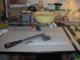
I have started to assemble another version for the frame. Hope this will be the last one :-). The first step was to cut the carbon tubes and to do this ,I used a plastic ruler and a saw with a small blade to cut metal. To adjust the sizes of the tubes I used a rasp tool for metal and a fine grit sandpaper for metal.
Figure 1
The Figure 1 shows the work in progress and the tools, as well as several carbon tubes already cut. It is also important to have at hand a vacuum cleaner to clean the carbon dust that is produced during the cutting and sanding and do not forget to put a mask because of dust.
Figure 2
In Figure 2 we can see the bottom of the frame now with the plastic pieces placed in appropriate locations.
Figure 3
In the last figure (Figure 3) we can see the bottom and the top of the frame. Nowhere in the construction glue is used to connect the different parts. To keep the tubes attached to the pieces I used kite line (the green line in figure 2 and 3) and the white nylon cable ties. I will continue to assemble the frame. Hope it will be ready this week!

Monday, September 20, 2010

Read data from the 9 DOF Razor IMU via Arduino board.

After several problems with the original 9DOF Razor IMU board, I have finally got a board with no functional problems or bugs. The challenge we had to work around then was how to read the data from the board? So I decided do some research and found in this blog that there was a simple way to read data using the Arduino Duemilanove connected to the 9DOF Razor IMU board without requiring any additional cable as shown in Figure 1.
Figure 1
The sketch to read the data from the 9DOF Razor IMU via Arduino Duemilanove is very short and simple as shown below.
/*

Read data from the 9DOF Razor IMU board via arduino duemilanove board.

1. Upload this Sketch to the Arduino board
2. Disconnect the USB cable from the PC. 
3. Connect the jumper wires between the two boards
   according to the following table:

9DOF Razor IMU | Arduino Duemilanove
---------------|--------------------
TX0............|TX1.................
RX1............|RX0.................
3.3V...........|3V3.................
GND............|GND.................
---------------|--------------------

4. Connect again the USB Cable to the PC.
5. Open Serial Monitor.
6. Send the character '1'.
7. Send the character '0' to view the 9DOF Razor IMU Menu.

*/

void setup() {
  Serial.begin(38400);
}

void loop() {
  if(Serial.available()) {
    Serial.print(Serial.read(), BYTE);
  }
}
After doing the upload of the sketch, and open the Serial Monitor, send a character between '1' and '5' followed by a '0' then a menu is shown (Figure 2).

Figure 2
In the menu there are have five options: [1] Accelerometer (ADXL345), [2] Magnetometer (HMC5843), [3] Gyroscope (LPR530 and LY530), [4] Raw and [5] Self Test. For example, if you choose the option "1" and if you move the 9DOF Razor IMU board in any direction you will see on the Serial monitor the variation of the values for the aceleration
The following video shows the 9DOF Razor IMU board connected to the Arduino board working hard (Sorry for the bad video quality!). Notice menu of the 9DOF Razor IMU board on the monitor of the laptop.
But unfortunately this sketch does not fit what I want. With the Arduino Duemilanove only can be used a single Serial connection at a time. However, that problem can be solved by using software libraries. One of the libraries is the SoftwareSerial library which allows the serial communication on any of the Duemilanove's digital pins. But, because it's not supported by hardware, the library has a few limitations. The other library is the NewSoftSerial library that emulates an additional serial port, allowing you to communicate with another Serial device. However, there is another Arduino board where you can use more than one connection, which is the Arduino Mega. With the Arduino Mega is possible connect more three Serial devices. The last solution is more robust but, requires a further investment in a new board. So I'll have to take a look in the Arduino board clones.

Tuesday, September 14, 2010

Building quadcopters for impatient people.

Image from the instructables.com site.
On Sunday I have received a newsletter from the website "Instructables.com" and one of the articles was about a school class who made a fully functional quadcopter in only 4 weeks using the arduino board and standard RC equipment. All the stages of its construction can be followed on this page of the website "Instructables.com". The code is also available. The video of the quadcopter, also including other projects, can be viewed at this link.

Monday, September 13, 2010

Fuzzy Logic Control.

While I was looking for information about PID controllers I have found the so called Fuzzy Logic method. Even it is a quite old method it has not been explored well enough. It can solve problems by using non-well-precised information, similarly to what happens when human brain has to make a decision. Thus, things like knowledge and daily experiences, coming for example from human feelings to temperature, light, etc, can be mapped into an abstract knowledgement such as exact numeric ranges as in this C# code example. In the real world most of the systems have nonlinear behaviors or are difficult to linearize, so is it here that this methodology is an alternative to traditional control methods. On this link you will find a more detailed explanation for its use. For myself it seems to be easier to understand and implement than a PID controller. I have found this paper with a practical application of that method to an autonomous robot obstacle avoidance, but one can be found many more examples of applications in different areas.
After a search on google I have found several libraries to implement this methodology:

Tuesday, September 7, 2010

Inspection of the plastic parts.

After some holidays I am finally back to work. The first task was to check the size of plastic parts and test their resistance to shock and traction.  I have noticed that the carbon tubes and the holes of the plastic parts do not fit as they have different sizes. Although this is an easy problem to solve by using a proper drill to increased the holes of the parts. Thus for further reference the tolerance of the holes must be increased by some millimeters.
The plastic parts are well resistant to shock as there is no visible damage when dropped from the second floor of a building to its ground floor. This test is also known as naive test :-). They are also well resistant to traction as the nylon thread used on the traction did not break the plastic part.
Therefore, the plastic parts we are using are suitable for the construction of the quadcopter. Now I'll have to order the other parts to complete the frame.