Friday, April 30, 2010

Control all four motors from the arduino board with ESC's.

After some research I was able to control all four brushless motors from the arduino board with four speed controllers, one for each motor. The sketch can be seen in detail below.
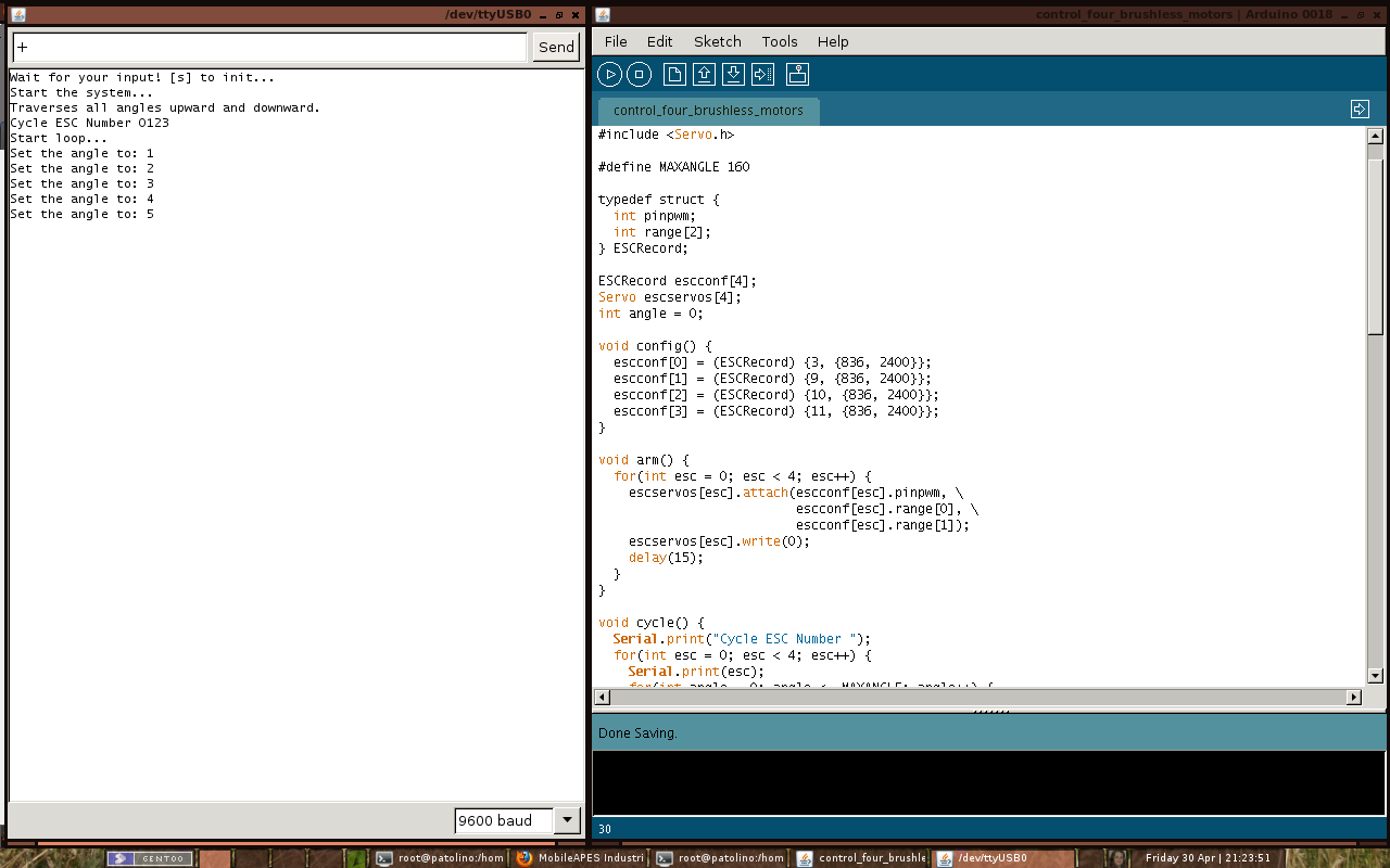
Figure 1
The figure 1 shows the arduino development environment. In the left window (Serial Monitor) you can see the result of the instructions sent to the arduino board via serial port (USB-serial device). When the quadcopter is switch on must be sent the character "s" to initialize the speed controllers. After the controllers initialized, do not re-send the character "s" in any circumstance, if you send the motors immediately accelerated to full speed in less than 1 second. If you have placed the propellers in the motors of the quadcopter, then you'll see him being sent to the deep sky if you're a lucky guy. Here is the warning to anyone wishing to use this sketch. To increase the speed the character "+" is sent to the serial port and the character "-" to decrement the speed. To stop the motors the character "0" is sent.
Figure 2
The figure 2 shows how the speed controllers are attached to the side panels.
Figure 3
The figure 3 shows the cable connections of the speed controllers on board (Sorry for the bad image quality). When I have time I do a diagram of all connections.

#include <Servo.h>

#define MAXANGLE 160

typedef struct {
  int pinpwm;
  int range[2];
} ESCRecord;

ESCRecord escconf[4];
Servo escservos[4];
int angle = 0;

void config() {
  escconf[0] = (ESCRecord) {3, {836, 2400}};
  escconf[1] = (ESCRecord) {9, {836, 2400}};
  escconf[2] = (ESCRecord) {10, {836, 2400}};
  escconf[3] = (ESCRecord) {11, {836, 2400}};
}

void arm() {
  for(int esc = 0; esc < 4; esc++) {
    escservos[esc].attach(escconf[esc].pinpwm, \
                          escconf[esc].range[0], \
                          escconf[esc].range[1]);
    escservos[esc].write(0);
    delay(15);
  }
}

void cycle() {
  Serial.print("Cycle ESC Number ");
  for(int esc = 0; esc < 4; esc++) {
    Serial.print(esc);
    for(int angle = 0; angle <= MAXANGLE; angle++) {
      escservos[esc].write(angle);
      delay(15);
    }
    for(int angle = MAXANGLE; angle >= 0; angle--) {
      escservos[esc].write(angle);
      delay(15);
    }
  }
  Serial.println("");
}

void setup() {
  delay(1000);
  Serial.begin(9600);

  Serial.println("Wait for your input! [s] to init...");
  while(Serial.available() <= 0)
    delay(1000);
  int incomingByte = Serial.read();

  Serial.println("Start the system...");

  config(); 
  arm();
  delay(5000);

  if(incomingByte == 115) {
    Serial.println("Traverses all angles upward and downward.");  
    cycle();
    delay(1000);
  }
  Serial.println("Start loop...");
}

void setspeed(int angles[4]) {
  for(int esc = 0; esc < 4; esc++) {
    escservos[esc].write(angles[esc]);
    delay(120);
  }
}

void loop() { 
  if(Serial.available() > 0) {
    int incomingByte = Serial.read();
    if(incomingByte == 43)      // sends the character '+'
      angle++;                  // increases the speed
    else if(incomingByte == 45) // sends the character '-'
      angle--;                  // decreases the speed
    else if(incomingByte == 48) // sends the character '0'
      angle = 0;                // set the speed to zero
    
    if(angle < 0)
      angle = 0;
    if(angle > MAXANGLE)
      angle = MAXANGLE;
      
    Serial.print("Set the angle to: ");
    Serial.println(angle);
  }
    
  int angles[4] = {angle, angle, angle, angle};
  setspeed(angles);
}

Monday, April 26, 2010

Cables and more cables.

Finally silicone cables have just arrived. Now I can solder the connectors on the cables to connect all speed controllers (ESC) to the battery. I'll cut four red cables (0.75 qmm) that will connect a red cable (1 qmm) that will connect to the battery. Then I will have to do the same for the black cable. I also ordered the cable to connect the receiver connection from the speed controllers to the arduino board, but came with the wrong colors, orange, red and brown, but what I ordered was black, red and white. After some research on google I found that the colors depend on the manufacturer of the radio control (R/C). So the orange, white or yellow color is the signal (Pulse), the red color is the Positive, the brown or black color is the Negative (Ground). For the quadcopter I just need the white cable (orange or yellow) and the black cable (brown) from the all speed controllers.

Monday, April 19, 2010

Now you can follow the blog on twitter.

I have just started a MobileAPES account on "Twitter". If you are a “Twitter” fan, click on this link to follow this project. I will use this tool to keep the readers and followers of the blog up to date on the progress in building of the quadcopter.

Tuesday, April 13, 2010

Control a motor from the arduino board with a speed controller.

I connected the speed controller (ESC) to the arduino board and I connected the black cable of the receiver connection to the GND pin of the arduino and the white cable to the Digital PWM pin number 3.

I upload a sketch that I found on this post from the Arduino Forum to the board to test the motor, but nothing happening.
After some research I discovered that is necessary adjust the minim pulse width value. From the operating instructions that came with the speed controller I find that the stop position must be within the range 800 us to 1700 us and the full-throttle position must be at least 350 us than the stop position.
I make another sketch to find the the minimum pulse width value that start the motor and closer to the 0 angle. After several attempts I found that the nearest value is 836 us.
Finally, I made the sketch that is shown below, which starts the  ESC and keeps the motor running in a loop for 30 seconds and then stop for 10 seconds.

#include <Servo.h>

Servo escservo;

long lasttime = millis();

void setup() {
  delay(1000);
  Serial.begin(9600);

  // If you connected now the battery to the ESC, send
  // the 's' character. If not send another character.
  Serial.println("Wait for your input! [s] to init...");
  while(Serial.available() <= 0) delay(1000);
  Serial.println("Start the system...");
  int incomingByte = Serial.read();
  
  // Change the min pulse width value until match the
  // lowest value needed to start the motor.
  // From the ESC operation instructions the stop position
  // must be within the range 800 us to 1700 us.
  // The value 836 us is the lowest value.
  escservo.attach(3, 836, 2400);
  
  // arm the ESC
  escservo.write(0);
  delay(5000);
  
  // If you sent the character 's'
  if(incomingByte == 115) {
    Serial.println("Traverses all angles upward and downward.");
    cycle();
    delay(1000);
  }
}

void cycle() {
  int angle;
  // Danger: Try first with a value lower than 179, eg 160
  // Gradually increase to 180.
  for(angle = 0; angle <= 160; angle++) {
    escservo.write(angle);
    delay(15);
  }
  // Decrease the angle from 180 to 0.
  for(angle = 160; angle >= 0; angle--) {
    escservo.write(angle);
    delay(15);
  }
}

void loop() {
  long duration = millis() - lasttime;

  // If the duration is great than 30 seconds,
  // stop the engine for 10 seconds.
  if(duration >= 30000) {
    escservo.write(0);
    delay(10000);
    lasttime = millis();
  }
  // Put the motor to rotate in the angle 5
  escservo.write(5);
  delay(500);
}